Showing posts with label Builds. Show all posts

BionX PL350 Based Build with Pack Powered Lighting

I've wanted to do a BionX based build for a while now, and finally got it done!  I built this as a "daily commuter" class bike for the Seattle area, tried a few things I wanted to try, and added a few touches of my own!


This build started with an older BionX PL350 36v kit that found it's way to me.  Only 230 miles on the clock, but the battery was stone dead (this is related to how it found it's way to me).  I rebuilt the battery, as I often do, with brand new cells.  It's now a 13.5Ah battery instead of the stock 9.6Ah battery, so this kit has about 35% more range than it did right from the factory!

I've also successfully demonstrated that one can do pack powered lighting with a BionX conversion - both headlights are powered directly from the main battery!


As always, keep reading for a lot more details & photos.


Basic Build Details

The bike for this build is a 2015 model Specialized frame I got on closeout.  It's a medium frame mountain bike with 26" wheels.  At the request of the eventual buyer, I swapped the original front suspension fork out for a solid fork, and added a disc brake to the front wheel.

It has my usual "commuter" touches as well - a bar end mirror, a bell, tightly fitted fenders that extend fairly far down (it does rain in Seattle, oddly enough), and heavily armored tires.  At this point, I consider those mandatory for anything that's going to be ridden regularly.  Fair weather bikes, ridden on separate trails, are boring!  And they're often carried to the trail on a bike rack, which is a silly way to transport a functioning bike.


One of the really nice things about the downtube battery BionX kits is that the weight of the bike is more balanced.  There's still the rear hub motor, but the battery pack is forward.  Contrast this to my commuter and you can see how the weight is better spread along the bike.

Brakes & Tires

I'd originally decided to try a rim brake build, because this kit has regenerative braking available from the motor.  Unfortunately, this didn't work out as well as I'd hoped.  The hills are just too much out here in Seattle.

As a result, it has a cable operated front disc brake now.  The rear brakes are still rim brakes, but the motor adds significant braking to the rear, and this arrangement seems to work out well enough.


The tires are Specialized Nimbus tires, with their Flak Jacket Puncture Protection.  They're 26x1.5, which is a narrower, road focused tire that's still capable of dealing with mud and trails in limited amounts.

Inside the tires, the tubes are a thicker, thorn resistant type, and are filled with a latex sealant that should seal any punctures that do happen.

This is basically the same setup I use on my commuter, and I've brought home a pretty good nail in that tire, so I know this layering works.


Pack Powered Front Lighting

Up until now, this has (mostly) resembled a standard, by-the-book BionX build.

You didn't really think I'd just stick with that, did you?

One of the reasons I did this build is to experiment with pack powered lighting on the older BionX systems.  I suspected it was possible, but I wanted to prove it.

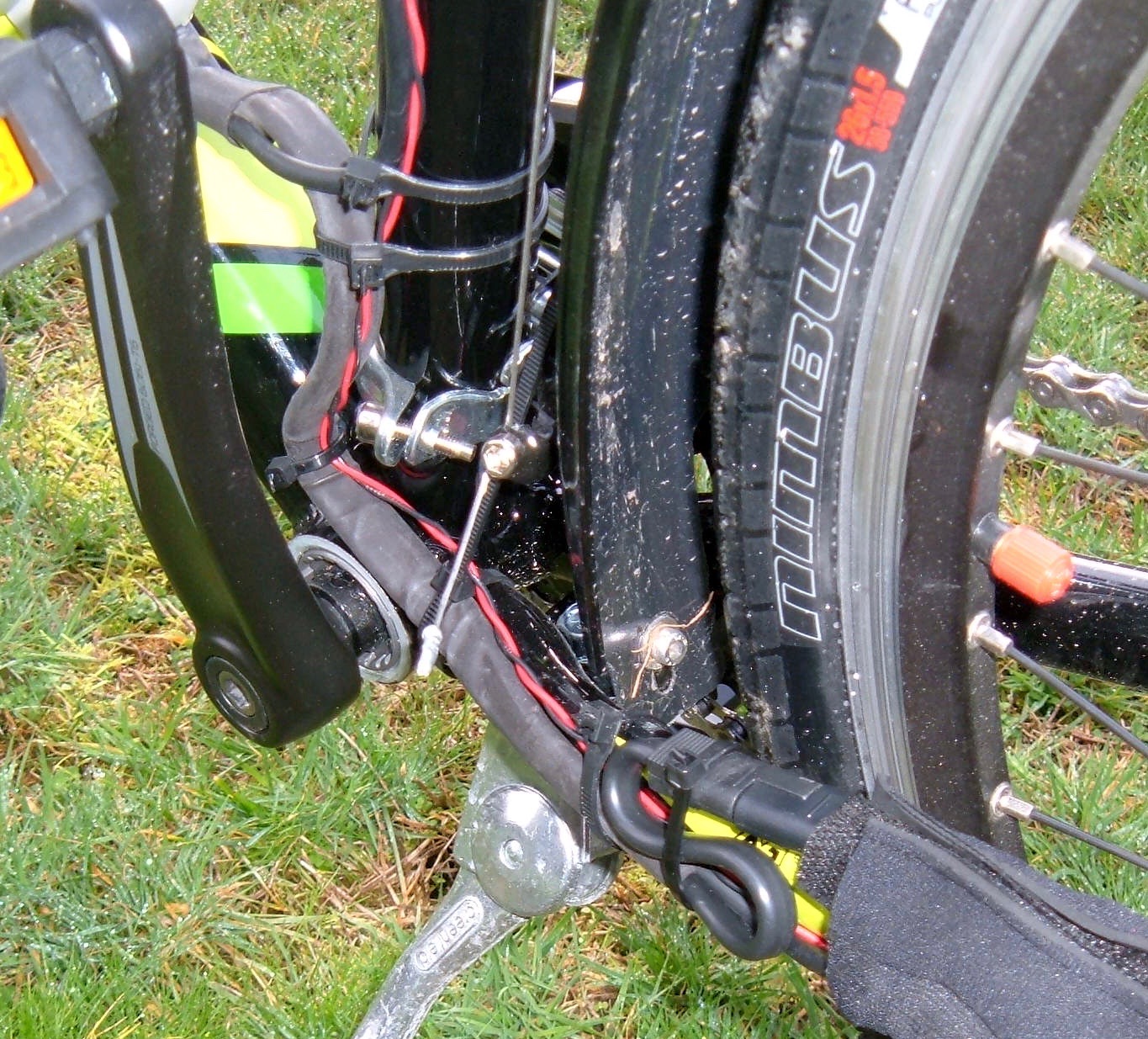
There are two cables running to the motor from the battery pack.  The first is a small, multi-pin control cable.  The second is a large, two pin cable that looks like the type of thing that carries power.  Which, in fact, it does.  Pack voltage, even!

When the bike is turned off, the pack is disconnected from the motor power cable.  But, when the system turns on, full pack voltages is available on these pins (so about 42v fully charged with the 36v battery packs).

This connector, at least on the older systems, is an SAE 2 pin connector.  You can find plenty of extension cables and the connectors on eBay for not much money at all.

I ordered one, built myself an extension cable with a tap for pack voltage, and then got so excited to install it that I forgot to take pictures.

It's remarkably difficult to get this to fit - the cable lengths are matched, and I went and stuck another few inches of power cable in there.  You can see the "S" curve that I made to take up the slack.  The red & black twisted conductors carry pack voltage up to the front of the bike for the lights.

The lights are a pair of "ebike headlights" I got from (surprise!) eBay.  I ordered a bunch of different types, and these are the best I found so far.

The advantage of "ebike headlights" or "scooter headlights" is that they take a wide range of voltages.  Other bike lights I've reviewed were quite picky about their voltage, and wouldn't handle anything outside their designed voltage without letting out the magic smoke.  With a slightly more complex voltage regulator circuit, this variety of headlight can handle anything from 12v to 80v as the input voltage (so it will work on almost anything out there).

I kept the front reflector installed, but moved it to the other side.  I don't need the space for anything else, and while the lights are on any time the bike is powered on, the battery can go dead, so it keeps a reflector.

That said, I'm not actually worried about the battery going dead.  This bike has regenerative braking that can be turned on at any time, so a light level of regen acts as a wheel dyno that will power the lights.  Unless you want the lights to go out, you can keep them on.
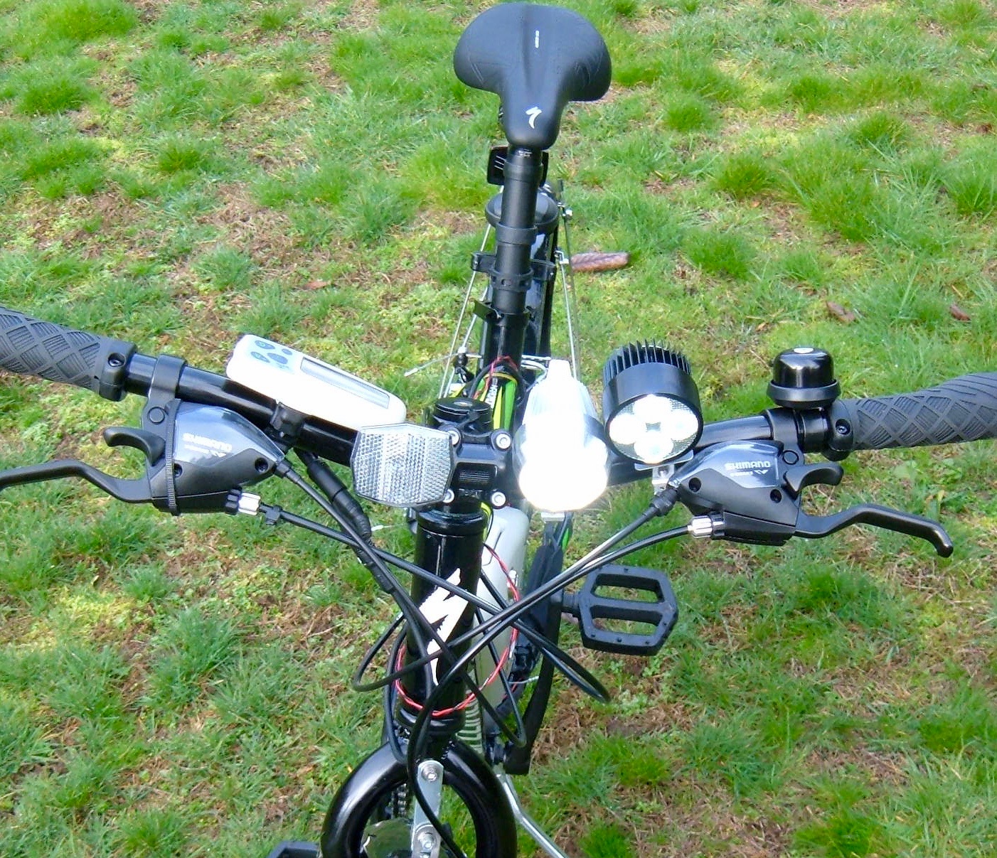

The mounts aren't fancy.  They're just some metal clamps and hex head screws.

But, you know what?  This is about $30 of headlights, and they're pretty damned good.  I've got over $200 worth of lighting on the front of my commuter (a $160 Cycle Lumenator, $50 of random LED lights, and a pair of DC-DC converters to power the lower voltage lights), and there's really no difference in the end result.

Power comes up from the twisted pair of wires, and is split to feed both lights.  There's a set of connectors under the waterproofing tape, in case the bars need to come off.


This provides a good idea of how the lights look at night.  The center core of illumination is overexposed compared to what it actually looks like, but this shows roughly how it looks from the biker's perspective, and about how far you can see.  It's really quite good, especially considering the cost, and more than adequate for the speeds this bike will do at night - even on a pitch black trail.

I've ridden my commuter and this bike on the same trail at night, and this set of headlights is just as good as my commuter set, for a fraction the cost.


Rear Lighting

The rear lighting is a lot less exciting.  I'm using one of the "Laser 5 LED Bike Lights" I reviewed a few weeks back, a random USB chargeable light bar, and the stock reflector.  I've been trying to find a good tail light solution for electric bikes that works over a wide voltage range, and haven't found a reasonably priced one yet.  Grin makes a really nice 8 LED tail light that works at almost any voltage, but it's $60, and I think that's a bit excessive (so, of course, my commuter has it).

In any case, there's plenty of rear lighting on this bike for what it's going to be doing.


Brake Lever & Regen Control

Because this bike has integrated brake levers and shifters, I can't just replace the brake lever with a BionX compatible one.  I need to use the magnetic pickup and provided magnet, which I've done.  This photo is looking at the right shifter/brake unit from the underside.  The cylinder held on with the zip tie and 3M molding tape, and the magnet is also held on with 3M molding tape.  That stuff is really, really useful - I end up using it somewhere on almost all my builds.

The magnet and pickup are set so that a small movement of the brake lever triggers the regenerative braking.  I adjusted the rear brakes a bit loose, so the first stage of lever travel is just motor regen, and it works nicely.


Riding & Hill Climbing

This bike is just nice to ride.  Turn it on, set the assist level, and go.  The BionX system gets out of the way entirely when riding, but there's a smooth assist rising up to help when you need it.  It is, by far, the nicest system I've ridden.  You pedal, it assists, the console does things to show you what it's doing, but you can safely ignore that and just ride the bike like it wants to be ridden.

The bike is happy cruising along at 17-19mph with a low level of assist, and seems to use remarkably little energy getting around (as is to be expected with a pedal assist).  The upgraded pack capacity helps, but I'd expect 20-25 miles of "level 4 assist" with some energy left over for lights, and if you turn the assist down, it'll go as far as you care to ride.

It climbs hills far better than I expected of a 350W system - to the point where I began to wonder if it's pushing more than 350W through the motor.  According to NYCEWheels, the newer 350W kits will peak around 700W, and I would believe it.  I didn't have time to attach a wattmeter to this bike, but it chewed up my muddy pipeline trail test (a long, insanely steep hill filled with mud and gravel) far better than I'd expected.  While it puts out noticeably less power than my 1000W bike, it'll still manage 8-10mph up my "commute hill," and that's a radical improvement over no motor.

The only real downside I've noticed is that it will thermally throttle if you abuse it too much (say, a long, slow climb up that muddy trail).  At some point, it decides things are getting too warm and it cuts the power output significantly.  This is a bit annoying at the end of a hill, but it really does beat frying the motor or controller.

I was excited by the throttle option initially (since I'm used to a throttle based bike), but it turns out I almost never used it.  The pedal assist is a better way to ride this bike.

Regenerative Braking on Bicycles

The PL350 has a regenerative braking mode.  It's activated by the either brake lever sensor or the console buttons, and one can control the strength of the braking regeneration in the settings menu (code 2002, values from 1-64).  Since this bike has rear rim brakes, I turned it all the way up, interested in how much dynamic braking power I could get.

I've long thought that regenerative braking on bicycles is a bit silly.  Yes, you can recover a tiny bit of energy, but the light weight and awful aerodynamics of a typical bicycle make it hard to recover much of what you've put in - rolling downhill, air drag takes most of the energy.

After riding this bike, with regenerative braking available?  Well, I still feel about the same.  It's a nice feature, but I wouldn't go with a direct drive motor just for this.  The amount of energy that can be recovered is minimal, and if you live on a hill and start out with a full pack, the regenerative braking is quite limited - there's nowhere for the energy to go.  So you use your brakes anyway.

If I had a heavy cargo bike and normally charged the battery pack to 90% for longevity reasons, regen might be a useful feature.  But for a single passenger bike, it's just not that important.  It saves your brakes a tiny bit, and that's about all it's worth.

My commuter bike is heavier, a bit faster, and has a geared hub motor - so no regenerative braking at all.  I live on top of a rather impressive hill, with a steep 220' vertical descent in the morning, and the same climb on the way home.  Despite this, I can get 8-12 months of daily commuting from a set of Koolstop Electric Bike Pads before I need to replace them.

If the kit you're looking at for other reasons offers regenerative braking, you may as well use it.  But I don't think it's worth seeking out a specific kit just for this feature, unless you're on a cargo bike.

Conclusions

This was a fun build!  I enjoyed getting to work with the BionX system, and to ride one on roads I'm familiar with (I put 30 or 40 miles on in testing before selling it).

Coming from a 1000W geared hub motor, I thought I'd be underwhelmed by the power delivery - but I wasn't!  It's noticeably less power than my commuter, but the smoother pedal assist really makes up for it.  I work a bit harder on this bike, but on "level 4 assist" it's not much more effort than my commuter build, and I really don't notice the difference.  The exercise is probably good for me anyway.

It climbs hills well, it rides nicely, and BionX has clearly done their homework when it comes to smooth operation.

It may be old, but the PL350 is still a great system!

If you have one that you'd like the pack rebuilt on, let me know with the contact form on the right.  Or, if you have a dead system you're getting rid of, let me know as well!

Trek Valencia Ride+ BionX Battery Pack Rebuild

It's near the end of January.  Oil is back over $30, Bitcoin is (yet again) doomed, and I've just spent the last two posts detailing a teardown of a Trek Ride+ Valencia battery pack.

If you haven't read them, you really read both to understand where this post is coming from.  It's hard to appreciate the rebuild without understanding the horrors of the teardown.

Trek Valencia Ride+ BionX Battery Pack Teardown: Part 1
Trek Valencia Ride+ BionX Battery Pack Teardown: Part 2


And now, I'm going to rebuild it.  Read on, because you know you want to see what happens!


Rebuild Overview

This rebuild is going to be a little bit different from my previous ones.  I'm not exactly duplicating the previous pack design, but instead using a different cell layout.  

The original pack is 4P11S - sets of 4 cells wired in parallel, then 11 of these sets in series.  I'm going to rebuild this pack as 11 cell series sets, and then wire the 4 of these in parallel.

There are several reasons for this.  The first is that I saw what happened to the 4P11S pack with the horror show of negative voltages across many of the parallel groups.  I haven't seen this on the other BionX packs I've torn down (which were series then parallel), so I'm inclined to go with the layout I know works.

The second reason is that the 4P11S layout is actually very difficult to build, and rebuilding it would be incredibly tricky.  Since there are 4 groups of 11 cells, doing them series then parallel makes it radically easier to build.

Finally, I reduce the resistance losses in the nickel strip significantly, since instead of the full pack current flowing through the nickel strip, only 1/4th the pack current is flowing through the strip - so losses are 1/16th (P=I^2*R).  Nickel is not the most conductive material on the planet, so reducing the losses there should help with the range.

These combined to make it, in my opinion, worth rebuilding the pack differently.

I keep the chemistry the same, using 2250mAh Sony US18650V3 cells to replace the 1600mAh Sony US18650V cells.  This means a 9Ah pack instead of a 6.4Ah pack, though!

Function Check

This pack is a newer CANBus pack.  I've heard about problems with them not working after a rebuild, so I set out to find out as much as I can about testing them first.  I obviously can't just stick it on a bike to test, since the batteries are stone dead.

What I found out is that on both the I2C and CANBus packs, shorting pin 3 to the nearest large pin (the negative terminal) will turn the pack on.  You get a few beeps out of it, and while I can't test detailed functionality, it's enough to verify that the BMS isn't totally dead.

Fortunately, for a two lead BMS (positive and negative), I can simulate a healthy battery without too much trouble.  Set my DC power supply to something in the pack voltage range, hook it up, and check it out!

Please note: I am NOT trying this with the battery attached.  The battery (which is stone dead) has been removed, and I'm testing with the bare leads to the BMS.  I'm not trying to charge the battery.  Don't do this and try to charge a stone dead battery, because it's not safe.


The BMS seems good!  It beeps at me and the tail light comes on.  This is about as good as I can hope for!

Building the Modules

To rebuild the pack the way I want to, I need 4 11S modules.  Things start, as they always do, with a box of batteries.


To line the cells up, my welder helpfully came with a cell jig.  I don't actually know where to find these as standalone objects to purchase, but they are most certainly useful!  Once they're lined up, the hot glue gun comes out and they're glued together.


A bit more hot glue later, and all 11 cells are attached firmly to each other.  This is a remarkably strong cell configuration once glued together.

The pack didn't come glued together.  It relied on the welded strips to hold the cells together.  This worked fine, but I prefer things to be stronger (and the configuration will be different, so I can't rely on the stripping for structural strength).  Glue it is.


Once things are glued together, the spot welder comes out and the strip gets welded in place.  You'll notice I'm using the trapezoidal ends on the strips again.  This is to prevent the sharp corner from punching through the positive protectors and shorting to the negative casing.  That's just too exciting for my taste.  I'm a very boring person when it comes to shorting out batteries.

Once both sides are welded, I've got a 11S cluster ready to go, except for the end tabs.  If you're doing this, please be sure you don't reverse the direction of the tabs on one side and end up with a bunch of dead shorts between two cells.  You'll only get through the first one, but I hear that it's also incredibly exciting.  Something about venting, flames, thermal runaway, and a really bad time.


Finally - all 4 modules are welded up and ready for the next step.


Connection Tabs & End Insulation

Despite what some people insist on doing, you can't solder directly to 18650 end caps.  All the manufacturers say not to, and it dumps a lot of heat into the cells that shouldn't be there.  I can touch one of the ends immediately after welding to it and it's faintly warm to the touch.  You might not want to try that with soldering onto the battery.

So, I need connection tabs to solder to.  I also need to insulate these things very well.

At the top of the picture, you can see two strips of insulating paper used to insulate the ends of the cells.  At the bottom, in red, is my connection tab protector.  This adds a layer of protection between the connection tab and the plastic wrapper around the negative terminal.  A short here is bad, so I want to ensure it won't happen.


With the tab on, you can see how it's protected by the thick insulating paper.  Once the wire is soldered on, I'll add more hot glue to keep this from moving at all.


The negative terminal doesn't need the additional protection.   It's already soldered to the case, so the only thing it can rub through to is what it's already connected to.  I'll secure it as well once the pack is assembled, though.


A bit more insulating paper, and the first layer is complete.


However, for the sake of redundancy and not having pack failures, I'm adding another layer.


There are now two full layers of insulating paper on each side of the module.  They'll face each other, so there are four layers plus whatever is holding the modules together.  This should prevent any shorts.  I do try to overbuild the packs because they're going into a rough environment - bicycles are not a particularly gentle method of transportation, and I intend my packs to last, safely.


Pack Assembly

With all the modules done, it's time to assemble them into a pack.  This is how they need to go.


I searched for something that would hold the modules together firmly, but also would have a slight cushioning effect on vibration.

My double sticky 3M trim tape proved perfect.  It's an incredibly sticky double sided foam tape that I use in a variety of projects, and still have a huge roll of.

Two strips of it between each module looks like it'll work perfectly.


A quick test fit before I expose the second adhesive side, and things fit wonderfully!


Excellent.  One nicely stuck together pack.  This thing is properly solid.


Crimp Connector Experimentation

The final step in the pack build is wiring up the connections.  This requires coming from 4 tabs on each side to a single wire going into the BMS.

I'm not worried about the current - each module will only take 2-3A total.  However, I do want to ensure I have a strong, safe, robust connection.  And nothing works better than experimentation.

This is what I'm starting with.  Two wires on one side, one on the other, and an uninsulated crimp connector barrel.


It turns out that this actually works perfectly for what I need.  The crimp barrel is oversized for the wires, but as it crushes, the single wire remains in the bottom and the two incoming wires slide off to the sides.  With a bit of careful crimping and forming, there's a tight round connection that holds all the wires very firmly.  This is exactly what I wanted - but it's still not insulated.


Fortunately, heat shrink works perfectly.  This is a nice bit of adhesive heat shrink tube and it insulates perfectly.  As it heats up, the glue inside melts, and when the heat shrink cools, it glues to the wires, ensuring it stays firmly in position and isn't going anywhere.

For the actual pack, I'll double heat shrink the connections.  There's plenty of room.


Electrical Wiring

I've started building the actual pack wiring now out of 14 gauge wire.  These are the junctions on the positive side, and are crimped and have a double layer of heat shrink tubing on them.  They should be fine.


And the connections are installed and heat shrunk.  I'm using a 4-2-1 join, much as you'd find on a nice exhaust header (I may rebuild ebike packs, but I'm still a car guy)!


The negative side is wired up similarly, but is "backwards" compared to the postitive side.

After the wiring is in place, the hot glue gun comes out again to secure the wiring against vibration and motion.  Hot glue is cheap, and I don't want things moving in relation to one another.


It's alive!  I've done the final 2 into 1 connection with crimp connectors of a different variety, and they're heat shrunk down.  The negative connection includes the thermistor, which will be properly placed later.


As a final step before inserting the pack in the housing, the top of the pack (where it faces the BMS) gets two layers of insulating paper.  If you get the idea that I don't want things shorting out, you'd be correct.


The new pack snug in half the casing.


And, about an hour later, I got here!

The pack is back together, tested as far as I can test it, and seems to work.  Getting it together involved removing a lot of the black goop that held things together initially.  It was a process of "Fit things, find what doesn't fit, remove some goo, repeat."  And, eventually, it's back together!

The pack isn't quite as water tight as it was - I did discover some rubber o-ring type material in the groove.  But, it looks like it works, and it should be a nice upgrade over the stock pack!


One other random thing I've learned: If the pack is chirping, warbling, or otherwise making a slightly disturbed alarm like noise every half hour or so - it needs charging!  This is it's "Please charge me..." alarm.  If you're hearing a random noise, can't identify it, and have one of these packs - plug it in, please.  Dead packs are no fun.

Thoughts & Conclusion

This pack is a pain in the ass.  There's no other way to describe it.  It's incredibly difficult to get apart, and it's a very non-trivial pack to rebuild.

I really don't understand why BionX went this way with the pack.  A bunch of foam padding would have worked just as well to keep the pack in position, but wouldn't have made this brutally difficult to get apart.  The layout is a transition between their early packs and their later packs with a full BMS (where you do need the parallel groups), but it doesn't seem to have worked well, based on the horror show of negative voltages.

I'm glad it's back together.  One down, one to go.

If you have one of these and it's dead, at least you know it's rebuildable.  Though, it's not going to be cheap.  The labor required to rebuild this pack is very significant, and the pack will never look the same again.

Building a DC-DC converter to run cheap lights from pack voltage

Winter is coming.  This means dark evening commutes, and a lot of biking in the rain.  And that, of course, means I built this!


What is it?  Two DC-DC converters, waterproofed with hot glue, to power my winter lights.  Interested?  Read on!


While my summer commuting lighting needs were handled just fine with the Cycle Lumenator and a BikeBlaze 1W strobe in the front, winter needs more.  Wet roads seriously suck up the light, and pitch black trails need long distance illumination.  I've got two additional lights mounted for winter and rain.

One is a "Cree 2000 lumen" light (not 2000 lumens, but it has a nice tight beam for long range illumination).  I reviewed this one a while ago.

The other is a "3x Cree 2000 lumen" light (maybe 2000 lumens, total, but it's a nice ditch light).

They both came with external battery packs.  They're not actually very good external battery packs (2P2S 18650s, and used batteries at that), so I had to charge them regularly.  I could get a few days on the small light from a charge, but only about one day for the 3x LED light.

Carrying and charging small battery packs when I have a huge 500WH pack on the back of my commuter bike is annoying.  So, I set out to build myself a nice voltage adapter before winter so I could run the lights off the main traction pack!

Adapter Design

At the start of the project, my light wiring consisted of a power cable run from the battery pack to the handlebars with pack voltage and a 5.5x2.1mm barrel plug.  This went straight into my Lumenator (since it works on pack voltage).

These extra lights aren't nearly so easy.  As I discovered when reviewing the 2000 lumen one, they're not very flexible about input voltage.  Which is to say, they start smoking around 12v.  Putting a 40v pack straight into them without voltage conversion is not an option (while failure is always an option, I prefer my LED headlights working and not smoking).  As they top out at 8.4v, a steady voltage of 8.0v seemed about right.

I set out to power everything from the one cable running forward.  This means a pack voltage feed into my Lumenator, and around 8v into both winter lights.  This calls for a Y cable and some voltage converters!

The more difficult part is the voltage conversion.  There are a lot of expensive DC-DC converters out there, and a lot of very, very cheap ones.  Of course, for one of my DIY projects, I went with the cheap ones.  I suffer a bit of a loss in efficiency, but my main pack has radically more power than I need for my commute, and "cheap is good" seems a decent first approach for something that might not even work.  Also, I wasn't interested in an expensive converter that cost more than the lights did.  I'm only powering $50 of lights here...

For "power-per-converter" reasons, I opted to use two converters - one for each light.  I probably could have gotten away with one, but it would have been pushing close to the power limit of the converters I ordered, and I'm rather uncomfortable pushing cheap Chinese devices beyond about 50% of "rated capacity" anyway.  They tend to blow up when you do that.

So.  That's my plan!  A Y cable and some DC-DC converters.  Oh, and whatever I build has to be weatherproof, because I do commute year round in the rain.  Yeah.  It sucks, but it still beats driving...

Before I continue, here's the various parts on a dollar bill so you've got an idea of the scale.  The 18650 is not actually used - just a reference for people in other countries!


Barrel Plugs and Y Cables

I picked up a bunch of cheap barrel plugs on eBay.  The plastic shroud screws off, and lets you get at the contacts inside.  You solder your wires to these.  By convention, the center pin is positive, and the exterior barrel is negative.  I followed this.
  

After putting the wires in, you screw the plastic barrel back on, and you have a completed barrel plug!


Several more solder joints later, a bit of electrical tape, and I've got a Y cable.  Perfect!  Actually, not, but I'll get to that later.


Avoiding Spectacular Failures

One thing I strive to avoid in my commuter ebike is spectacular failures.  I'm not a fan of the Endless Sphere style builds in which failure is seemingly the goal, battery fires are just one of those things you deal with (like flat tires, and chain wear), and doing 60mph on a cheap build while trailing smoke and flames seems to be some sort of ideal.  I've got a kid.  And I don't like parts failures.  I especially don't like failures while commuting back and forth to work, which is the whole point of my bike.

Let's take a quick look at the barrel plug as soldered.  Pay close attention to the metal spikes that should wrap around the black wire.  They're a bit of vibration away from punching through the red wire when crammed together - and that would be a short circuit.  Short circuits are bad (unless you'r Johnny 5 and happen to be alive).  So I fixed it.


The first step is to do what you're supposed to do, with these and flatten the prongs down.  This is an improvement, and should be fine in most reasonably static conditions.


However, Seattle commuting is not most conditions.  It's very wet, and my particular path to work has a lot of vibration.  So, to help prevent vibration damage as well as to waterproof the back end of the connector, I added hot glue.  It prevents the wires from moving relative to each other, and is also a good insulator, so this should work nicely, even in the wet.

All of the barrel plugs were given this treatment.  Note that you don't need much hot glue - too much, and the plastic protector won't go over the plug.


Wiring the DC-DC Converters

I cannot say enough good things about having a decent, temperature controlled soldering station.  It makes this work so much easier!

I'm using two DC-DC converters for this project - one for each light.  They're sharing a connection to the pack voltage (it's well below 1A of my pack voltage for both, so not a problem).  I want to be able to run both lights at full brightness if I want to, and the 2A output from a single converter is not enough (especially when applying my Standard Chinese Electronics derating of 50%).

Soldering the leads onto the ends of the converters is straightforward.


A few more connections, and I've got the electrical bits finished.  The left side is pack voltage, and the right side is headlight voltage.  Perfect!  Though... not very waterproof.  And not at all insulated.


A bit of testing later, and I'm set!  I adjusted the units to right around 8v output with a full pack.  This is within the comfortable working range of the headlights.  If it's not obvious, you adjust the output voltage with the little screw on top of the blue gizmo.  It takes a lot of turns!

Recall that I don't like short circuits.  I'm about to do something that could lead to short circuits if I'm not careful...

Waterproofing the DC-DC Converters

The easy way to mount these boards is back to back.  Unfortunately, if I do this, both the input and the output sides are "positive to negative" when referenced between the two boards.  Now, I'm no Electrical Engineer, but I am a Computer Engineer.  And, I can assure you, that's Bad.  Short circuit, smoke, flames, the works.  So, I need to keep those terminals from touching - ever.


My first attempt at this involved wrapping electrical tape around the boards, with one side open.  After I got the spacing right, I filled the space between the boards with hot glue.  In addition to keeping them in place, it's slightly flexible so vibration shouldn't be a problem, and it insulates.

I'd considered a number of options.  The best approach would be some sort of potting compound.  Another option would be epoxy, but most epoxies cure very brittle, and that plus expansion from thermal loads while operating is a good way to either crack the epoxy or rip parts off the board.

Hot glue has a few useful qualities.  It's an insulator.  It dries slightly soft, so thermal expansion isn't a problem.  It's also very, very cheap.  And, as I use it for my various pack rebuilds, I have a lot of it around.

Amazingly, it worked.  This approach to bonding boards together actually worked successfully the first time!  The fill wasn't perfect, as you can see in the photos below, but it was good enough to hold them at the proper distance.  Fortunately, fixing gaps in hot glue is as easy as squirting more hot glue in, so I cleaned this up later.


The next step is to waterproof the electrical side of the boards.  Electrical tape worked once, so maybe it will work again?

I built a dam around the first board with electrical tape - something like this.


After finishing the dam, I started filled it with hot glue, and kept filling until it was above all the parts.  Then, it's just a matter of twiddling my thumbs for a while while it sets up.


After the glue fully set, I pulled the tape off.  It's not perfect, but it's actually a lot better than I was expecting!  The sides didn't get quite filled in, but everything else looks quite well protected.

Electrical tape leaves an interesting texture on the hot glue.  I kind of like it.


A little bit of touch up with with the hot glue gun (to fix those exposed areas), and one unit is good to go.


The other side was the same process.  After I got the bulk of it covered, I went around and filled in all the gaps, ensured the boards were fully waterproofed, and ensured the wires were coated with hot glue out to the insulation.  I don't ride in torrential downpours, but my bike does get wet regularly.

It's not the prettiest thing I've ever built.  It's actually tremendously ugly.  But, it's cheap, and it works!  And now I have pack powered lights!


This is the final result.  A Y cable, and a colorful blob of hot glue with connectors coming out of it.


Mounting and Testing

After playing around with it, I found a good spot on the top of my bar clamp.  This has several important advantages:
  1. It's up in the cooling airflow.  I'm not sure how much power it will dissipate, but it gets the best shot at staying cool up here.
  2. I can see if it's melting, shorting, or otherwise misbehaving, ideally before it bursts into flame.  If it does catch fire, I'll be very aware of this fact in a hurry.
  3. It should deter anyone who was considering stealing my bike.  If I'm the type of guy who zipties this up front and center, what's the rest of the bike like?
The hot glue should protect it from vibration and water, and it's fairly well secured with the zip tie.


And, the worst possible type of "LOOK AT MY NEW LIGHTS!!!" photo: A head on shot of them, blinding the camera!  Yes.  They're all running off the pack, with the exception of the BikeBlaze, which is my strobe and "Aw, I ran the pack flat..." light.


How does it work?

Well, quite nicely, now.  Initially, I had problems with my Lumenator.  My barrel plugs aren't long enough to fully seat in the Lumenator, so it kept cutting out.  I gave up in the face of pending winter, and ordered a Y cable from Grin directly.  This replaced my Y cable, and with that addition, everything works wonderfully!  There's a 2-3mm length difference between my connectors and the Grin connector, and this makes a huge difference.

The huge blob of hot glue will get a little warm to the touch if I run the lights at max brightness for my full commute, but I don't generally do this, so I should be fine at my normal power settings.  Most of the use will be when it's cold and rainy anyway, so heat isn't a big problem.

As for lighting?  It's excellent.  With the aux lights on dim, I have a great beam pattern in front of me from the three lights, and can easily see where I'm going in the dark.  It's exactly what I was hoping for (though I knew the lights could do it from playing with the battery packs last winter).

So far?  No problems at all!

Cost

How much did this thing cost?

Assorted wire, hot glue, etc: $2

Total cost: $8.12

... plus a $9 Y cable with the proper ends, and shipping.  *grumbles*  So about $35.

Conclusion

So far, so good!  I'm happy with this after a few weeks, and it's working wonderfully in the evenings.

I can't say I'd build this for someone else, but if you're looking for a cheap way to power cheap lights from your pack, this route absolutely works wonderfully!  Just check your barrel plug length...